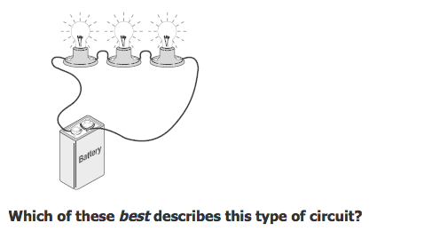
Best Describes the Measured Current Flow in a Series Circuit
An open circuit will cause current to flow F. To measure the current flowing through a component in a.
What is the purpose of a transistor in an electronic circuit.

. The total resistance is equal to the sum of the individual resistance values. 1 x 0 to 5A ammeter. It is measured in Coulombssecond which is named Amperes.
The unit of electric current is the ampere A. Students will describe the components of a circuit describe the role of switches in electric circuits compare series circuits with parallel circuits construct series and parallel circuits. What best describes Voltage.
In parallel current flows into a branching point. Which of the following statements best describes the difference between series and parallel. You use a.
Characteristics of a Series Circuit The current is the same everywhere in a series circuit. Which of the bulbs will light. An ammeter is used to measure the current flow in circuit.
Series have single path parallel have two or more paths. The current flowing through any branch of any circuit or. It controls the direction in which current flows in the circuit.
It resists prevents or limits current flow in a circuit b. 1 and 3 only. This circuit uses direct current DC so you need to.
By using Ohms law the current flowing is the ratio of the voltage drop to the resistance of the sense resistor. Set your multimeters range selector to a DC milliamp range of at least 20 mA. A series circuit has no branches.
It is measured in Amps c. The calculation is shown here. The flow of electrons.
The current in a series circuit depends upon the number of cells. Start studying Current and Circuits. For example of a 10Ω resistor is placed in circuit and a reading of 100 mV is detected across it then using Ohms Law it can be deduced that the current is V R 01 10 10 mA.
All of the above 4. Current total charge that has passed a point time taken I ΔQ Δt or ΔQ I Δt UNITS. Current is the amount of charge measured in coulombs passing a point in the circuit each second.
Electric circuit a closed path through which electrons can travel. 2 and 3 only. A device called an ammeter is used to measure current.
The voltage of the batteries is increased when they are connected in series so they last less time than when they are connected in parallel. The load solenoid On the positive side of the load. This is an example of lead placement in a series circuit.
However scientists always draw the current in the opposite direction. We can measure the current in a circuit by using an ammeter. Measured in parallel to a circuit.
The sense resistor is placed in series with the circuit in which the current is to be measured causing a voltage drop. Voltage measured from motor negative terminal to chassis ground. The total power is equal to the sum of the power dissipated by each resistance.
The total voltage is equal to the sum of the IR voltage drops across the individual resistances. 1 2 and 3 only. Some types of ammeter have a pointer on a dial but most have a digital display.
Using highly stable and linear resistors which are available as standard circuit components it is easy to measure current flow. By measuring the voltage across the resistor the current can easily be calculated. Using Ohms Law you can determine the voltage drop across each resistor.
We call that the conventional current. An ammeter is connected in series with the circuit because the purpose of the ammeter is to measure the current through the circuit. 1 x 12V DC power supply.
A low-value resistor in series is used to sense the current. By using Ohms Law either the voltage current or resistance of any series connected circuit can easily be found and resistor of a series circuit can be interchanged. For the following statements decide whether it best describes Resistance R Voltage V Current I or Power P.
Electric current is the rate of charge or flow past a given point in an electric circuit. In using the Ohms law equation ΔV I R to determine the current in the circuit it is important to use the battery voltage for ΔV and the equivalent resistance for R. When the current flow through a low-value resistor it produces a voltage difference across the resistor.
The current measured at any point in a simple circuit will be the same because current is the measure of electron flow through a circuit. This moves from the negative end of the cell to the positive end. The same total current must flow out again.
2 x 5 ohm or 10 ohm fixed resistors. Then series resistor networks can also be thought of as voltage dividers and a series resistor circuit having N resistive components will have N-different voltages across it while maintaining a common current. In a series circuit current flows in multiple paths F 14.
I current measured in amperes A or Amps ΔQ charge past a point in the circuit measured in coulombs C Δt time taken measured in seconds s. Learn vocabulary terms and more with flashcards games and other study tools. Opposition to the flow of electrons.
Current depends on resistance in each branch. Apparatus Equipment To examine the voltage and current flow in a series and parallel circuit of resistors. Current measurement technique inserting series resistor into the circuit.
The amount of energy stored per charge. It stops the flow of electric current in the circuit. To measure the current in the LED circuit follow these steps.
It is the pressure that forces current to flow in a circuit d. To examine the voltage and current flow in a series and parallel circuit of resistors. In series current is the same at all points.
Therefore when 1A of current flow through a 1-ohm resistor. Measured on series to a circuit. The current in a DC series circuit.
A series circuits current flow is constant which implies its the same at each resistor. Is the same at all points. Lets take an example.
Youll get the same current reading whether you insert the ammeter between the LED and the resistor between the resistor and the battery or between the LED and the battery. As per ohms law Voltage is equivalent of current x resistance. Since the ammeter is a low impedance device connecting it in parallel with the circuit would cause a short circuit damaging the ammeter andor the circuit.
How Does Electric Current Flow through. 1 x 0 to 12V voltmeter. This is an example of lead placement in a parallel circuit.
Voltage measured from motor positve terminal to chassis ground. Suitable conducting leads to connect. The current in this series.
An electric current is a flow of electric charge around a circuit. You are testing a 12 volt running motor system in a series circuit using a voltmeter and identify the following circuit conditions. Suppose 1A of current is flowing through a 1-ohm resistor.
It acts as a switch or can amplify current in the circuit. The pressure pushing the electrons through the circuit. I tot ΔV battery R eq 60 V 40 Ω 15 amp The 15 amp value for current is the current at the battery location.
If you make the cells face in the same direction the more cells you add the greater the current.

Four Circuits Draw A Line From Each Electrical Circuit To The Correct Circuit Diagram Draw Only Four Lines Source Sat Ks Paper2 Q1 Tiers Ppt Download


Comments
Post a Comment